
4K UHD HDMI/HDBaseT 3.0 Extender with IR/eARC/ARC/PoC/RS-232/Ethernet/USB 2.0 and Audio Embedding/De-embedding up to 330ft


and engineering support

Overview
Experience unparalleled audio and video transmission with the BG-EXH-100C6 HDBaseT 3.0 extender by BZBGEAR. This state-of-the-art device unleashes uncompressed HD/UHD audio and video, along with eARC/ARC, RS-232, bi-directional IR, 1Gb Ethernet, and USB 2.0 signals up to an impressive distance of 328ft(100m) using just a single CAT6A/7 cable. Say goodbye to messy wires and hello to convenience.
With USB 2.0 host/device configurability, the BG-EXH-100C6 offers maximum flexibility and functionality, making it the perfect solution for a KVM setup. And, with bi-directional power over cable (PoC), there's no need for a second power adaptor, saving you time and money.
The BG-EXH-100C6 can support resolutions up to 4K@60Hz 4:4:4, and boasts HDR10, HDR10+, Dolby Vision and HLG technology, ensuring unparalleled picture quality. The transmitter can also embed or de-embed audio, while the receiver supports audio de-embedding. Plus, with eARC/ARC from the receiver's HDMI output, you can enjoy top-notch audio quality on your local audio system, or opt to use the transmitter's HDMI audio only and SPDIF output ports.
BG-EXH-100C6 by BZBGEAR is the ultimate choice for anyone seeking top-of-the-line audio and video extender. With its advanced features and unparalleled performance, it's sure to exceed your expectations.
Features
-
![fluent-mdl2_connect-virtual-machine]() HDMI Loop-outLoop-out to view content locally at transmitter side
HDMI Loop-outLoop-out to view content locally at transmitter side -
![IR-PASS-THROUGH]() Bi-Directional IRControl devices via IR either from the receiver or transmitter
Bi-Directional IRControl devices via IR either from the receiver or transmitter -
![material-symbols_shield-lock-outline]() HDCP 2.2High-Bandwidth Digital Content Protection Supported
HDCP 2.2High-Bandwidth Digital Content Protection Supported -
![bi_hdmi]() Rich Color ContrastHDR, HDR10, HDR10+, Dolby Vision, and HLG supported
Rich Color ContrastHDR, HDR10, HDR10+, Dolby Vision, and HLG supported -
![bi_badge-4k]() Stunning Image QualityCrystal clear images at 4K 60Hz 4:4:4
Stunning Image QualityCrystal clear images at 4K 60Hz 4:4:4 -
![img8]() Power Over CablePower only needs to be supplied to the either transmitter or receiver allowing for easier installation
Power Over CablePower only needs to be supplied to the either transmitter or receiver allowing for easier installation
- Transmit signals up to 328ft (100m)
- HDMI ARC from receiver to transmitter
- Utilize two USB 2.0 ports on both transmitter and receiver
- LED lights on transmitter and receiver to verify connection status at a glance
- Audio Embedding and de-embedding through S/PDIF optical port and 3.5mm stereo mini on transmitter
- 1Gbps LAN ports on receiver and transmitter to connect extra devices to a network
Videos


Tech Specifications
| Technical | |||
| HDMI Compliance | HDMI 2.0b | ||
| HDCP Compliance | HDCP 2.2 | ||
| Video Bandwidth | 18Gbps | ||
| Video Resolution | Up to 4K@60Hz 4:4:4 | ||
| HDBaseT Bandwidth | 16Gbps on main and 2Gbps on return link | ||
| HDR | HDR, HDR10, HDR10+, Dolby Vision, HLG | ||
| Color Space | RGB, YCbCr 4:4:4, YCbCr 4:2:2, YCbCr 4:2:0 | ||
| Color Depth | 8/10/12-bit | ||
| Audio Formats | LPCM, Dolby Digital/Plus/EX, Dolby True HD, DTS, DTS-EX, DTS-96/24, DTS High Res, DTS-HD, Master Audio, DSD | ||
| L/R Audio Formats | PCM 2.0 | ||
| SPDIF Audio Formats | LPCM2.0, AC3 5.1, DTS 5.1 | ||
| IR Level | 12Vp-p | ||
| IR Bandwidth | 20K - 60KHz | ||
| USB Bandwidth | Up to 350Mbps | ||
| Ethernet | 1000Mbps | ||
| RS-232 | Up to 921600bps | ||
| Transmission Distance | 330ft / 100m (via a single CAT 6A/7 cable) | ||
| ESD Protection | Human body model — ±8kV (Air-gap discharge) & ±4kV (Contact discharge) | ||
| Connection | |||
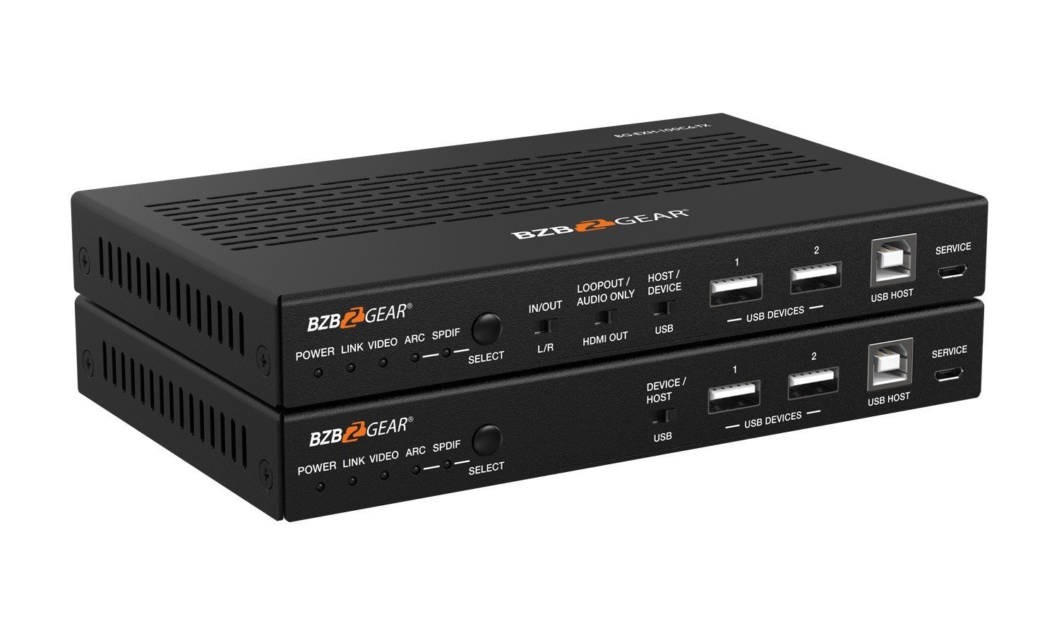
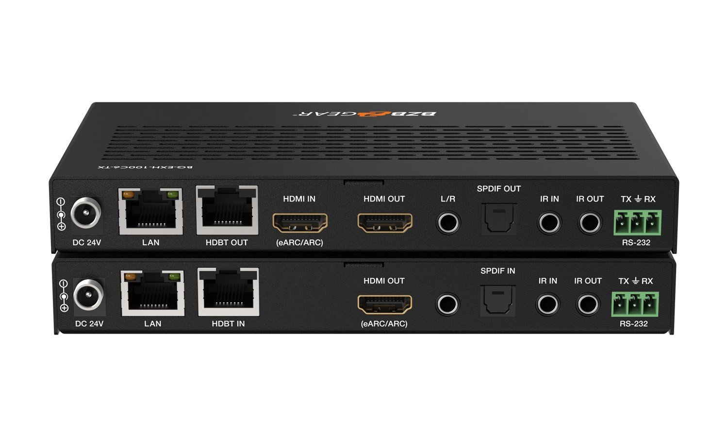
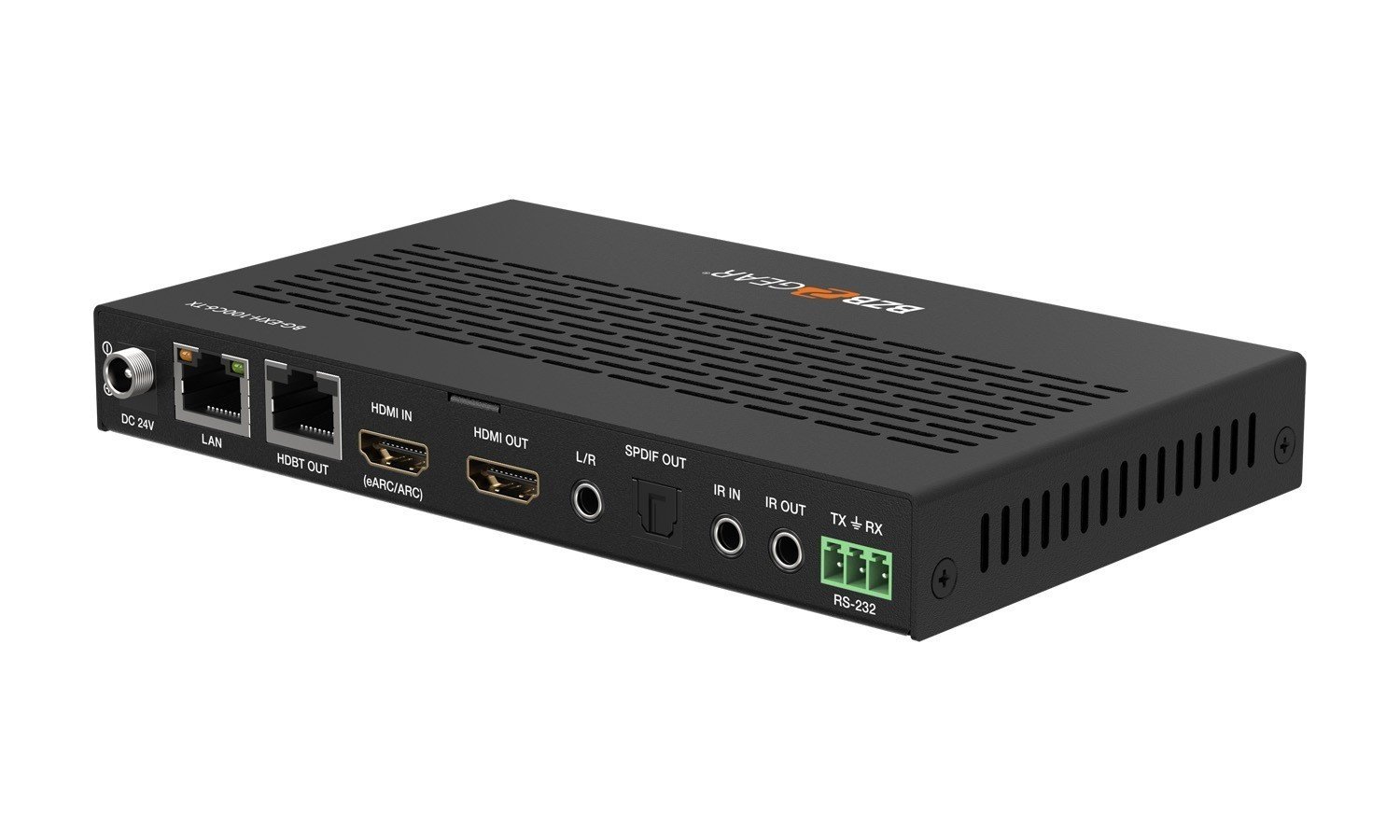
| Transmitter | Input: 1 x HDMI IN [Type A, 19-pin female] Output: 1 x HDMI OUT [Type A, 19-pin female] 1 x HDBT OUT [RJ45, 8-pin female] 1 x SPDIF OUT [S/PDIF] 1 x L/R OUT [3.5mm Stereo Mini-jack] Control: 1 x IR IN [3.5mm Stereo Mini-jack] 1 x IR OUT [3.5mm Stereo Mini-jack] 1 x RS-232 [3pin-3.81mm Phoenix jack] 1 x SERVICE [Mini-USB, Update port] 1 x USB HOST [USB Type B] 2 x USB DEVICES [USB Type A] 1 x LAN [RJ45] |
||
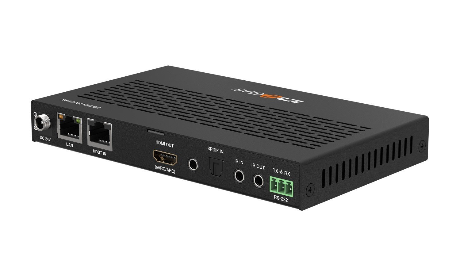
| Receiver | Input: 1 x HDBT IN [RJ45, 8-pin female] / 1 x SPDIF IN [S/PDIF] Output: 1 x HDMI OUT [Type A, 19-pin female] 1 x L/R OUT [3.5mm Stereo Mini-jack] Control: 1 x IR IN [3.5mm Stereo Mini-jack] 1 x IR OUT [3.5mm Stereo Mini-jack] 1 x RS-232 [3pin-3.81mm Phoenix jack] 1 x SERVICE [Mini-USB, Update port] 1 x USB HOST [USB Type B] 2 x USB DEVICES [USB Type A] 1 x LAN [RJ45] |
||
| Mechanical | |||
| Housing | Metal Enclosure | ||
| Color | Black | ||
| Dimensions | Transmitter / Receiver: 6.7"(W) x 4.0"(D) x 0.87"(H) [170mm (W) x 102mm (D) x 22mm (H)] | ||
| Weight | Transmitter: 0.94 lbs [425g], Receiver: 0.96 lbs [437g] | ||
| Power Supply | Input: AC 100 - 240V 50/60Hz Output: DC 24V/1A (US/EU standard, CE/FCC/UL certified) |
||
| Power Consumption | 15.36W (P0C) | ||
| Operating Temperature | 32 - 104°F / 0 - 40°C | ||
| Storage Temperature | -4 - 140°F / -20 - 60°C | ||
| Relative Humidity | 20 - 90% RH (no condensation) | ||
| Resolution/Cable Length | 4K60 - Feet / Meters | 4K30 - Feet / Meters | 1080P60 - Feet / Meters |
| HDMI IN / OUT | 16ft / 5M | 32ft / 10M | 50ft / 15M |
| Note: The use of “Premium High-Speed HDMI” cable is highly recommended. | |||
Resources


PACKAGE CONTENTS
- 1 x HDBaseT 3.0 Extender (Transmitter)
- 1 x HDBaseT 3.0 Extender (Receiver)
- 1 x IR Blaster Cable (1.5 meters)
- 1 x IR Receiver Cable (1.5 meters)
- 2 x 3pin-3.81mm Phoenix Connectors
- 4 x Mounting Ears
- 8 x Machine Screws (KM3*4)
- 1 x 24V/1A Locking Power Supply
- 1 x User Manual
Interfaces
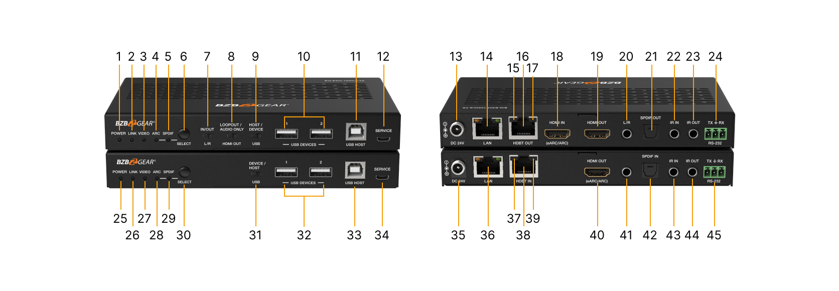
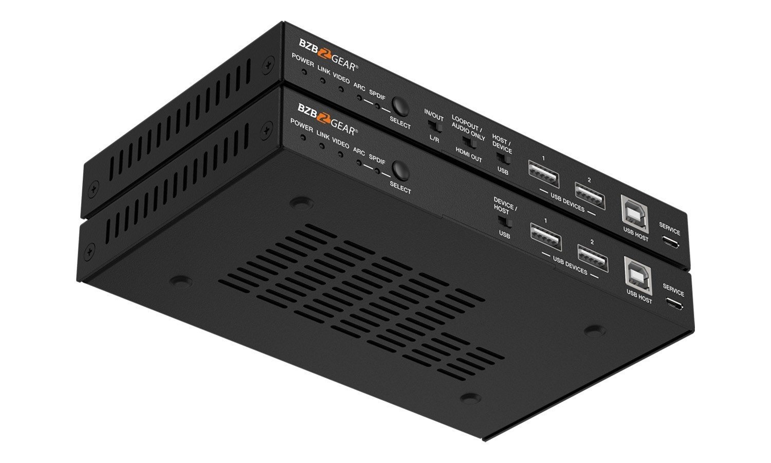
- Power LED: Red LED indicates that the Transmitter is powered on.
- LINK LED: Light on: Transmitter and Receiver are in good connection status.
Light flashing: Transmitter and Receiver are in Low Power Mode.
Light off: Transmitter and Receiver are not connected. - VIDEO LED: Light on: The video is encrypted.
Light flashing: The video is not encrypted.
Light off: No HDMI input. - ARC LED: Light on: The device is switched to the ARC mode
Light off: The device is switched to the SPDIF mode. - SPDIF LED: Light on: The device is switched to the SPDIF mode.
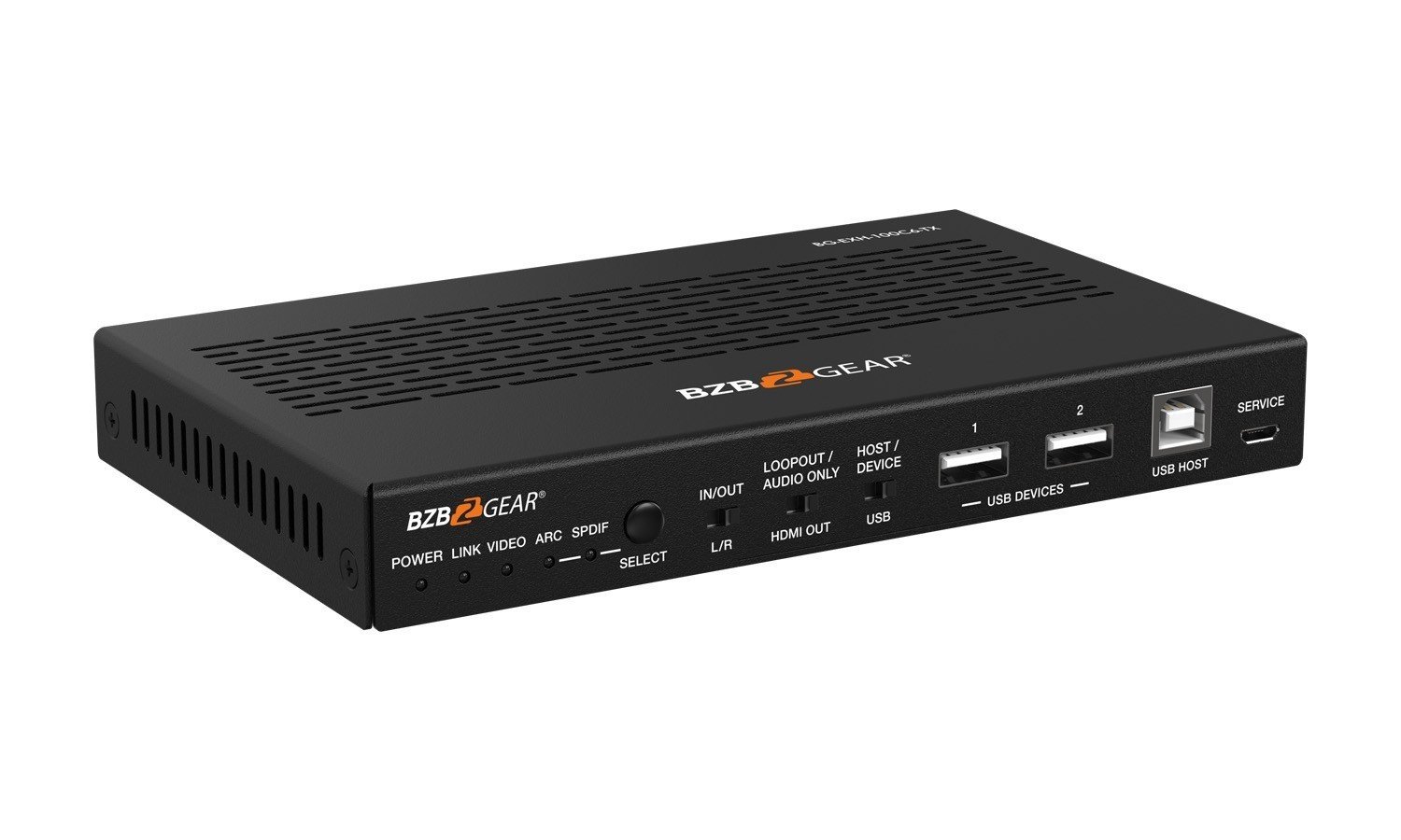
Light off: The device is switched to the ARC mode. - SELECT button: Used for switching the ARC mode and SPDIF mode.
- L/R IN/OUT switch: Switch to left, the L/R IN/OUT port is the audio embedding port; Switch to right, the L/R IN/OUT port is the audio de-embedding port.
- LOOP OUT/ AUDIO ONLY switch: Switch to left (LOOPOUT), the HDMI OUT port is the loopout port for the HDMI IN port; Switch to right (AUDIO ONLY), the HDMI OUT port outputs 720P black screen image, and the audio is from ARC or SPDIF.
- HOST/ DEVICE USB switch: Switch to left (HOST), the USB HOST mode is enabled; Switch to right (DEVICE), the USB DEVICE mode is enabled.
- USB DEVICES: Two USB device ports, connected to U disk, mouse or keyboard.
- USB HOST: USB extension host port, connected to PC.
- SERVICE: Firmware update port.
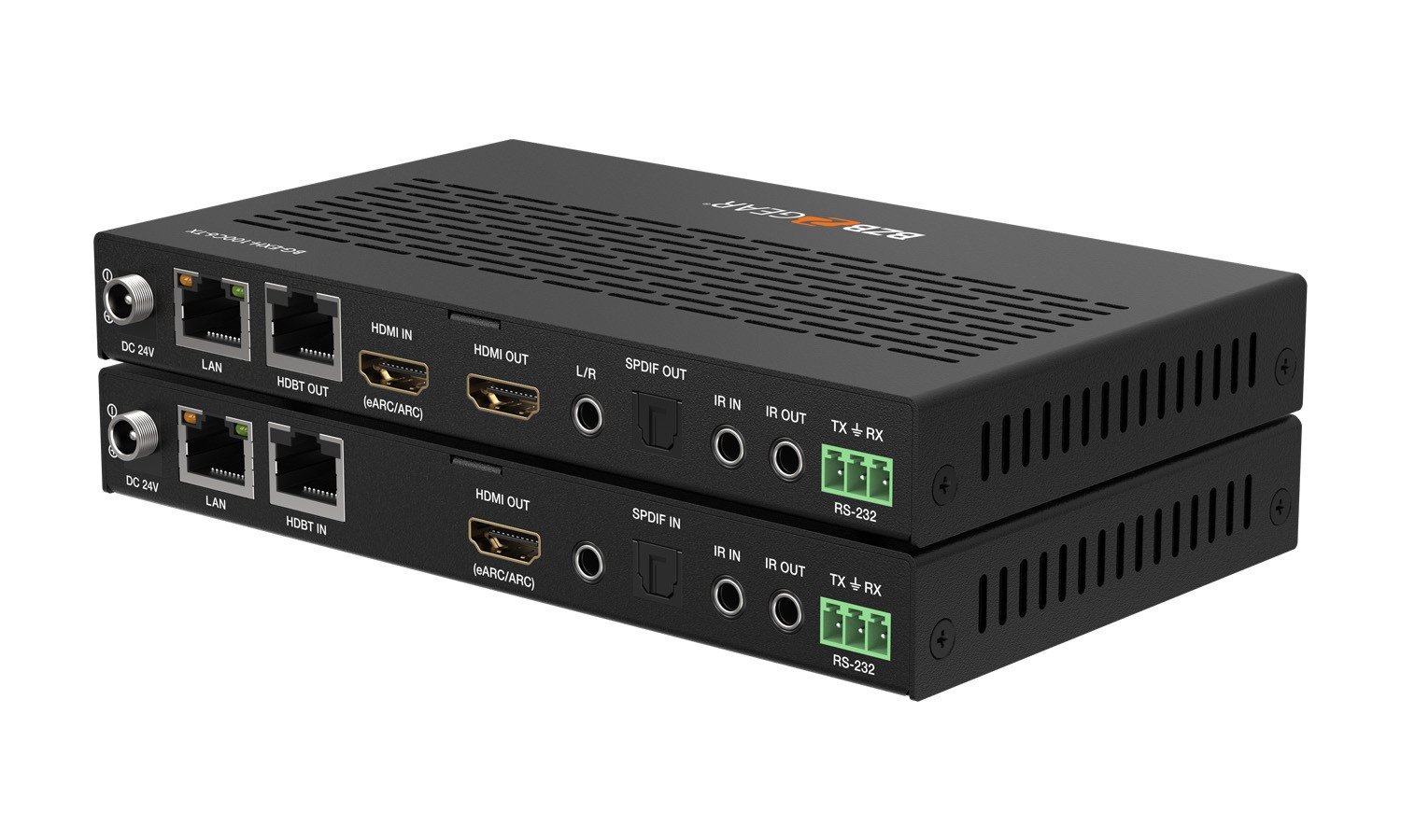
- DC 24V: DC 24V/1A power supply input port.
- LAN: 1G Network port. When it switches to Gigabit Ethernet, the green indicator lights on; When it switches to 100M Ethernet, the yellow indicator lights on.
- Data Signal Indicator (Yellow): Illuminating: HDMI signal with HDCP.
Flashing: HDMI signal without HDCP.
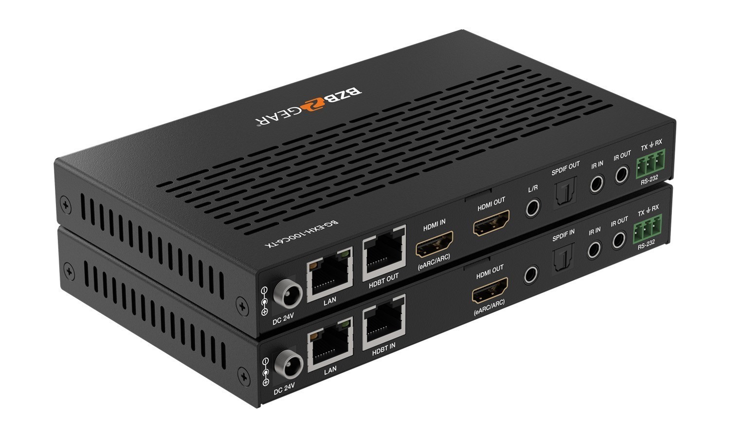
Dark: No HDMI signal. - HDBT OUT: 10G Network port, connected to the HDBT IN port of Receiver with a CAT 6A/7 cable. It is used for various signals pass-through.
- Link Signal Indicator (Green): Illuminating: Transmitter and Receiver are in good connection status.
Flashing: Transmitter and Receiver are in poor connection status.
Dark: Transmitter and Receiver are not connected. - HDMI IN: HDMI signal input port, connected to signal source device, supporting eARC/ARC amplifier.
- HDMI OUT: HDMI signal loopout port. It can choose to be a LOOP OUT or AUDIO ONLY port through the LOOP OUT/AUDIO ONLY switch.
- L/R IN/OUT: Audio embedding/de-embedding port. It can be used for audio embedding/de-embedding through the L/R IN/OUT switch.
- SPDIF OUT: Optical output port.
- IR IN: IR signal input port, connected to IR Receiver cable.
- IR OUT: IR signal output port, connected to IR Blaster cable.
- RS-232: RS-232 serial port, used for serial port command transmission.
- Power LED: Red LED indicates that the Receiver is powered on.
- LINK LED: Light on: Transmitter and Receiver are in good connection status.
Light flashing: Transmitter and Receiver are in Low Power Mode.
Light off: Transmitter and Receiver are not connected. - VIDEO LED: Light on: The video is encrypted.
Light flashing: The video is not encrypted.
Light off: No HDMI input. - ARC LED: Light on: The device is switched to the ARC mode.
Light off: The device is switched to the SPDIF mode. - SPDIF LED: Light on: The device is switched to the SPDIF mode.
Light off: The device is switched to the ARC mode. - SELECT button: Used for switching the ARC mode and SPDIF mode.
- DEVICE/ HOST USB switch: Switch to right (HOST), the USB HOST mode is enabled; Switch to left (DEVICE), the USB DEVICE mode is enabled.
- USB DEVICES: Two USB device ports, connected to U disk, mouse or keyboard.
- USB HOST: USB extension host port, connected to PC.
- SERVICE: Firmware update port.
- DC 24V: DC 24V/1A power supply input port.
- LAN: 1G Network port. When it switches to Gigabit Ethernet, the green indicator lights on; When it switches to 100M Ethernet, the yellow indicator lights on.
- Data Signal Indicator (Yellow): Solid: HDMI signal with HDCP.
Flashing: HDMI signal without HDCP.
Dark: No HDMI signal. - HDBT IN: 10G Network port, connected to the HDBT OUT port of Transmitter with a CAT 6A/7 cable. It is used for various signals pass-through.
- Link Signal Indicator (Green): Solid: Transmitter and Receiver are in good connection status.
Flashing: Transmitter and Receiver are in poor connection status.
Dark: Transmitter and Receiver are not connected. - HDMI OUT: HDMI signal output port, supporting eARC/ARC TV.
- L/R OUT: Audio de-embedding output port.
- SPDIF IN: Optical input port.
- IR IN: IR signal input port, connected to IR Receiver cable.
- IR OUT: IR signal output port, connected to IR Blaster cable.
- RS-232: RS-232 serial port, used for serial port command transmission.
Recommended Products